A lack of forethought, little or no Design Engineering, poor choices by business leaders, pretty much the entire wind energy industry started off on the wrong foot.
Now we're stuck with propeller on a stick forever.
All I'm going to say is watch what I'm planning to plant on my roof. None of the above mistakes will be repeated.
My father pointed out the available wind power is proportional to the cube of the velocity. So, speed up the wind and you'll have useful power. We actually built and tested his augmented twin-rotor VAWT designs. I finally came up with my own single rotor design incorporating all our lessons.

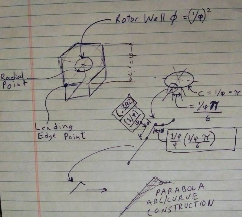
So this is a hexagonal design, nice and sturdy, extremely easy to build. The model here is about 1/4 scale of what I would really like to build, because four feet is the max you can easily cut a hexagon from a using a 4x8 sheet, i.e. a four foot diameter circle will inscribe said hexagon. There is a single Vertical Axis rotor at the center. There are six divider walls. No matter which direction the wind is coming from, two funnels will always be concentrating the flow, increasing pressure, density, and velocity, because two funnels will always be intercepting 60 + 60 = 120 degrees of the incoming flow. If there were four or five dividers it wouldn't work because the divider angles need to be sharp enough to cut the wind without spoiling it. Facing away from the wind, the dividers reverse function and lower the pressure, helping pull the wind out of the rotor, providing a widening expansion route for the exhaust wind. The dividers are "j"-shaped with a hook that slingshots the air sideways so it doesn't hit the rotor dead on. This slingshot action improves torque and energy extraction efficiency.

The design is compact, sturdy, and stealthy. It is inherently modular, so units can be stacked forming it's own hexagonal tower without increasing footprint. The top can accommodate solar panels. To a limited extent the interior southern floor area can also accommodate additional solar.
The dimensions are derived from the golden ratio φ. The overall diameter OD is φ. The divider height is 1/φ. The diameter of the rotor well is (1/φ) squared.
Starting with a divider leading edge point, imagine a line running to center. A radial point is formed by the intersection at the rotor well circumference. Now, going from center back out, the "j" hook shaped feature begins about 1/3 of the way on the divider from the radial point on the rotor well circumference, said r. The reciprocal of φ over φ to be exact, approximately 0.382 Now, consider 0.382 of the 1/6th circumferential arc of the rotor well running from said radial point. Here you have the smaller leg from which to construct a parabola; the larger leg being the previously mentioned .382 length from the leading edge of the divider.

Here is the full scale prototype with one turbine. Six more turbines can be installed. The wires and strain reliefs are actually there for mechanical structural reasons only.
Create Your Own Website With Webador